
Motherboards have many different components for attaching other parts, and for those seeing one for the first time, it can be hard to tell what is what.
When building a custom PC, many different names are used, so it is important to first learn the names of each slot and connector.
Also, knowing where these are located on the motherboard and what they look like will help make understanding and assembly much smoother.
If this knowledge is lacking, it is possible to buy the wrong parts and be unable to assemble the custom PC, which could mean having to buy parts again.
To avoid this, start by learning the names of the main parts of the motherboard, which is the core of a custom PC.
This article also explains motherboard standards, the names of each component, and how to choose based on performance and compatibility.
≫ Related article: How to Choose a Motherboard for a Custom PC [Performance / Features / Compatibility]
Select PC parts and online stores to instantly generate an estimate, check compatibility, and calculate power requirements. You can save up to five different builds, making it easy to try out multiple configurations.
≫ Tool:PC Parts Estimation & Compatibility Check Tool
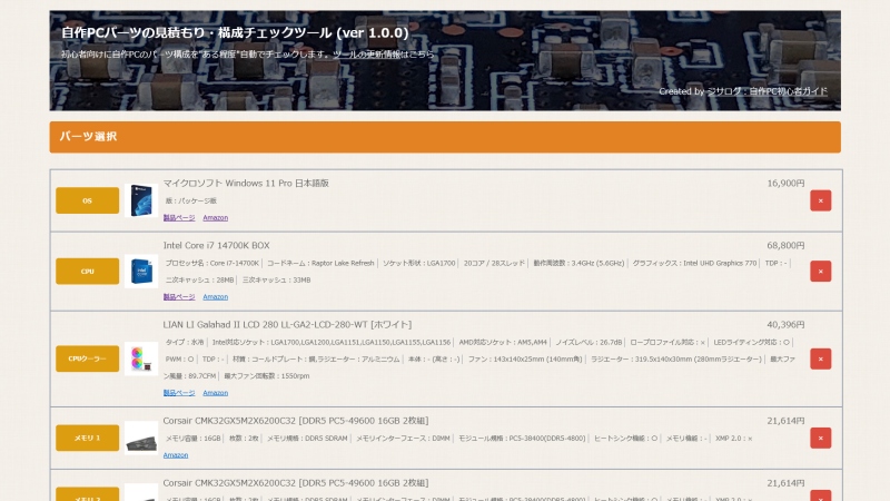
Table of Contents
Names of Motherboard Slots and Sockets
Motherboard slots and sockets are used to connect other PC parts like the CPU and memory.
Knowing where to install each PC part helps make assembly smoother.
CPU Socket
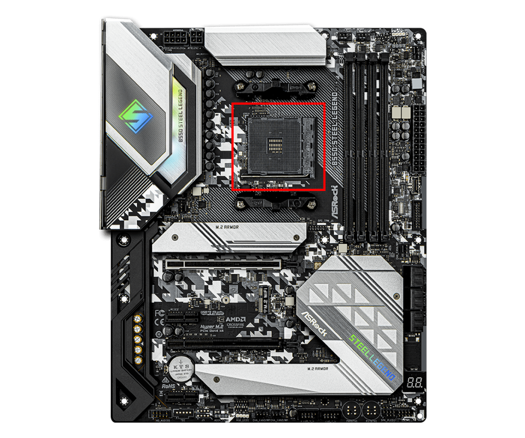
The CPU socket is the part of the motherboard where the CPU is installed, and it is designed to fit specific CPU models.
The shape and pin layout of the socket differ depending on the type of CPU, so when choosing a motherboard, it is necessary to select one with a socket that matches the CPU to be used.
Therefore, if the CPU is already chosen, a motherboard with a matching socket shape must be selected. If the motherboard is chosen first, a compatible CPU must be selected.
For example, Intel CPUs use sockets like “LGA 1700” or “LGA 1200,” while AMD CPUs use “AM4” or “TR4.”
≫ Related article: How to Choose a CPU for a Custom PC [Performance / Features / Compatibility]
Memory Slot
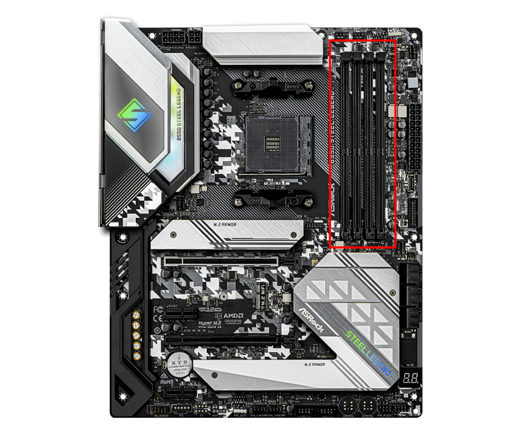
Memory slots are parts on the motherboard for installing memory, and they determine the type and number of memory modules that can be installed.
Most standard motherboards have 2 or 4 slots, but server and workstation motherboards may have 8 or 12 slots.
This allows users to add more memory as needed and improve performance.
The type and number of memory slots vary depending on the motherboard’s standard and design, with the latest standards using DDR4 or DDR5.
If the memory standard supported by the motherboard and the memory itself are different, it will not physically fit, so be careful.
≫ Related article: How to Choose Memory for a Custom PC [Performance / Features / Compatibility]
PCI Express Slot
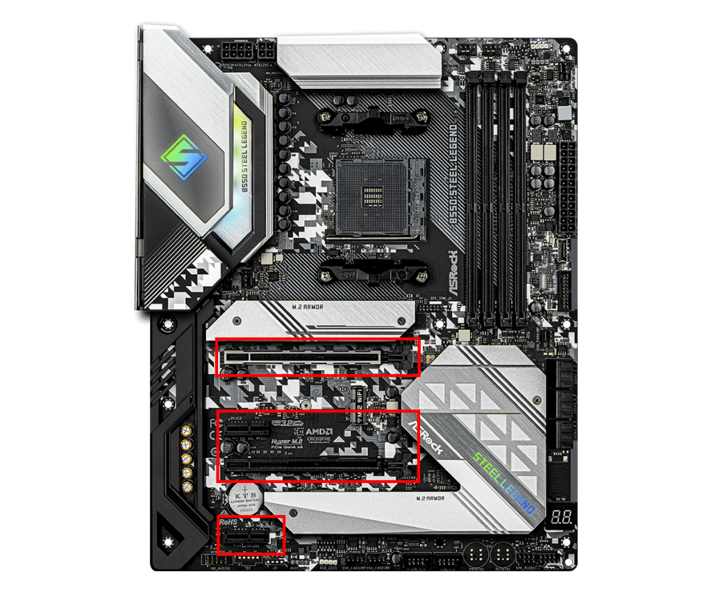
The PCI Express slot is used to connect expansion cards, such as graphics cards, network cards, Wi-Fi/Bluetooth cards, and capture boards.
It handles data transfer with expansion cards and provides power to operate them.
Slot sizes include PCI Express x16, x8, x4, and x1, with larger numbers indicating physically larger slots.
Generally, slots are classified by lane count (x1, x4, x8, x16), and more lanes mean faster data transfer speeds.
Graphics cards usually use x16, while wireless LAN cards and capture boards often use x1 or x4.
PCI Express also has versions from 1.0 to 6.0, with different data transfer speeds.
Currently, 3.0, 4.0, and 5.0 are commonly used.
These versions are compatible with each other, so expansion cards will work even if the versions do not match.
However, if the versions do not match, the lower version will be used, so keep that in mind.
In general, when building a custom PC, the version does not need to be a major concern.
If using a newer CPU, the socket shape will require a relatively new motherboard, which will have the mainstream PCI Express version at that time, so there is usually no need to worry.
M.2 Slot
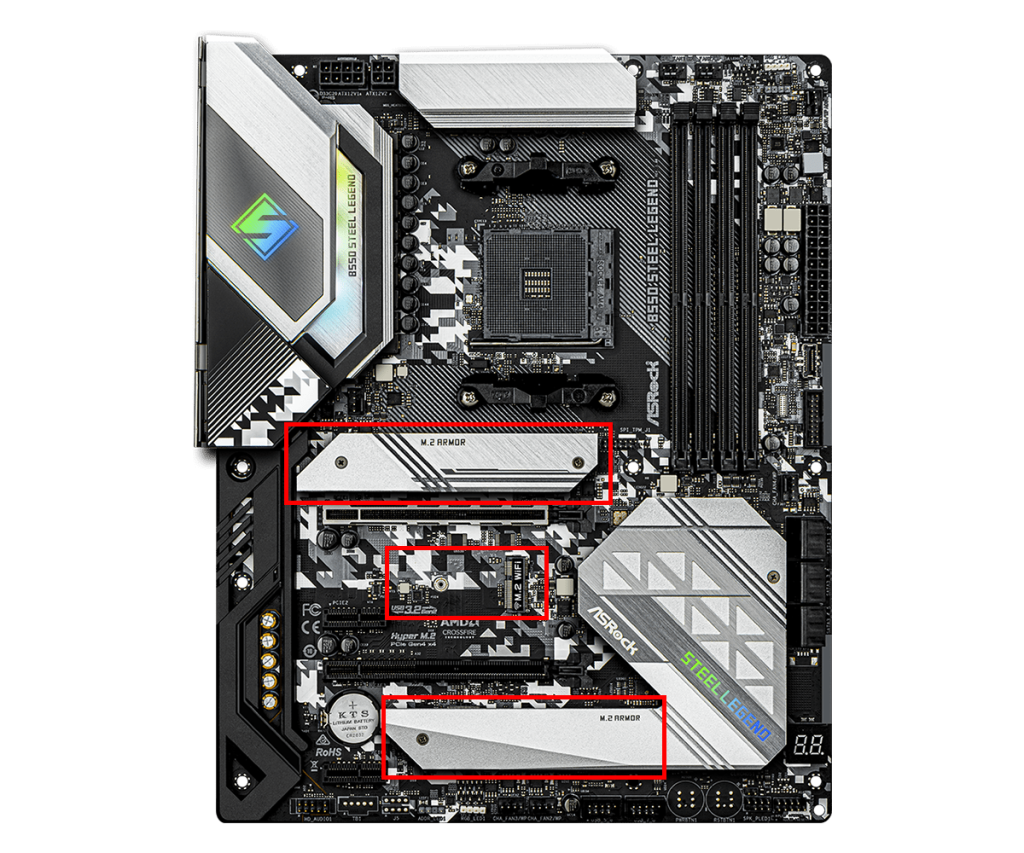
The M.2 slot is a small, high-speed slot for connecting NVMe SSDs and Wi-Fi modules.
It is mainly used for installing SSDs (solid-state drives), enabling faster data transfer than traditional SATA connections.
This slot supports the NVMe (Non-Volatile Memory Express) protocol, which allows for even higher performance.
Recently, NVMe SSDs are often used as the main storage for the OS and games.
Depending on the motherboard, there may be one, two, or three M.2 slots.
Smaller or lower-priced motherboards often have only one slot.
The M.2 slot is also used for connecting Wi-Fi modules.
There are several standards for M.2 slots based on the shape (notch) and size, and the type for NVMe SSDs is different from that for Wi-Fi modules, so be careful.
Besides M.2 slots, storage devices (SATA SSD/HDD) can also be connected via SATA connectors, so the number of M.2 slots does not limit the total number of storage devices.
Wi-Fi Module Slot
The Wi-Fi module slot is a type of M.2 slot used to add Wi-Fi functionality to the motherboard.
By installing a Wi-Fi module in this slot, even a custom-built desktop PC can have wireless internet connectivity.
Using the Wi-Fi module slot allows for internet connection without cables, making it easier to place the custom PC anywhere.
≫ Related article: PC Parts to Add Wi-Fi and Bluetooth to a Custom PC
Names of Motherboard Connectors
Motherboards have many connectors for supplying power and transferring data.
Most connectors are located around the edges of the motherboard, and it is good to know the main ones.
Cables from the power supply unit are connected to the motherboard’s connectors. The types of cables are explained here.
≫ Related article: Types of Power Supply Unit Cables
Main Connector
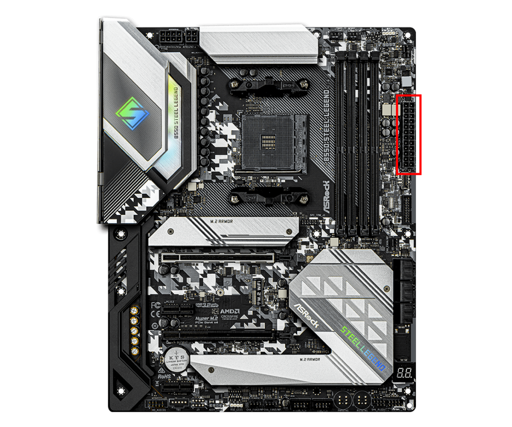
The main connector is the primary connector for supplying power to the motherboard.
This connector supplies power from the power supply unit to the motherboard and distributes the necessary power for other parts to operate properly.
It is also called the ATX power connector, and the 24-pin connector is standard.
Older motherboards used a 20-pin connector, but recent models use the 24-pin connector to supply more power.
CPU Power Connector
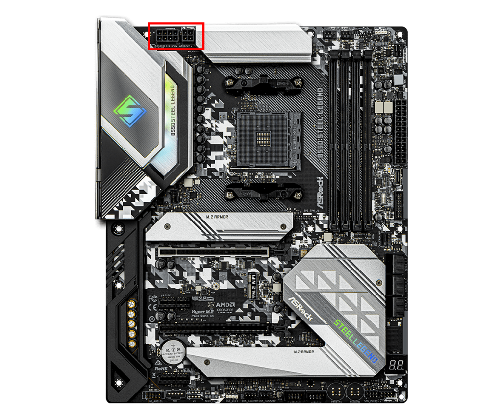
The CPU power connector is an important connector for supplying stable power to the CPU.
By connecting the cable from the power supply unit to this connector, the CPU receives the power it needs directly.
It is also called the ATX12V connector and comes in 4-pin or 8-pin shapes.
High-performance CPUs or overclocking may require two power connectors for sufficient power supply.
CPU Fan Connector
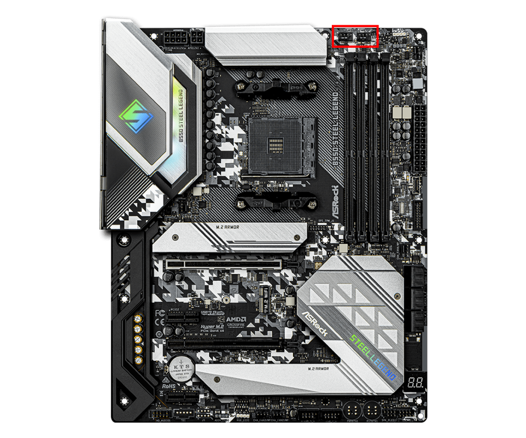
The CPU fan connector is used to connect the CPU cooler’s fan.
It is usually designed as a 4-pin PWM connector, allowing for power supply and precise fan speed control.
The system monitors the CPU temperature and automatically adjusts the CPU cooler fan speed according to the temperature.
This helps maintain proper temperature and keep high performance.
Fan Connector
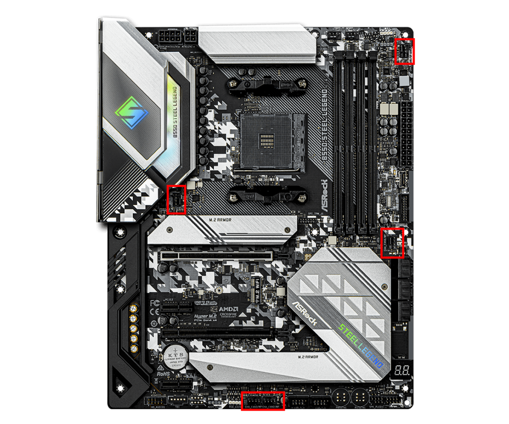
Fan connectors are mainly used to connect PC case fans.
They are usually 3-pin or 4-pin, and 4-pin connectors allow PWM fan speed control.
This allows fan speed to be adjusted as needed, balancing quiet operation and cooling performance.
However, the case fan must also support PWM.
Usually, there are about 3 to 5 fan connectors, with one connector used per case fan.
If more case fans are needed, fan splitters, fan hubs, or fan controllers can be used to connect multiple fans to one connector.
SATA Connector
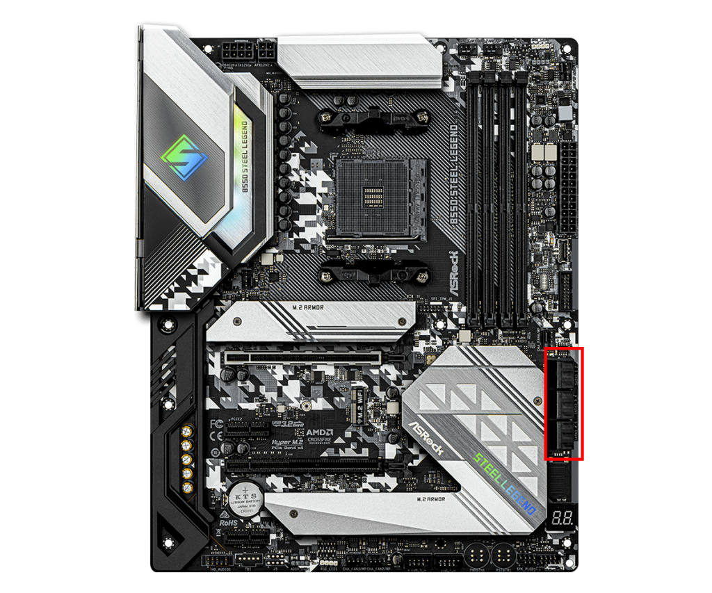
SATA connectors are used for data communication with storage devices such as SATA SSDs, HDDs, and optical drives.
Motherboards usually have 4 to 8 SATA connectors, allowing multiple storage devices to be connected at the same time.
USB 2.0, 3.0 Connector
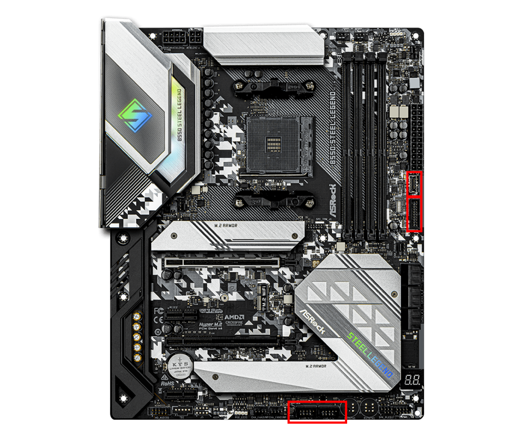
This connector is used to enable the USB ports on the front of the PC case.
There are USB 2.0 and USB 3.0 ports on the front of the PC case, but they will not work unless connected during assembly.
Inside the PC case, cables come from the front panel, and by connecting them to the motherboard’s USB connector, the front USB ports become usable.
USB 2.0 and 3.0 connectors are different, so check the version of the front USB ports on the PC case and make sure the motherboard has the matching connector.
![]() Ken
Ken
Front Panel Connector
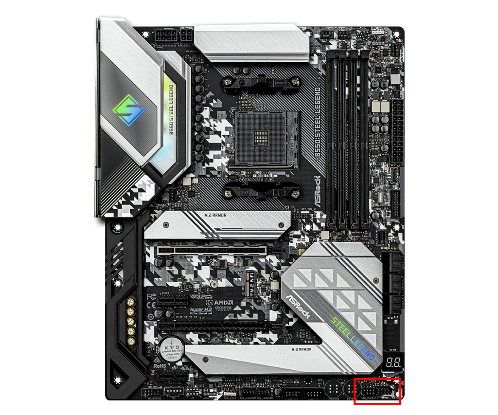
The front panel connector is used to connect the power button, reset button, and LED indicators on the front panel of the PC case to the motherboard.
These connectors are usually grouped together on part of the motherboard, with a fixed pin layout.
Each pin has a specific function. For example, the power switch pin sends a signal to the motherboard when the power button is pressed.
When connecting, refer to the motherboard manual and connect each cable to the correct pin.
Each connector is small and it can be hard to tell which pin is which, so be careful not to make mistakes.
Audio Header Connector
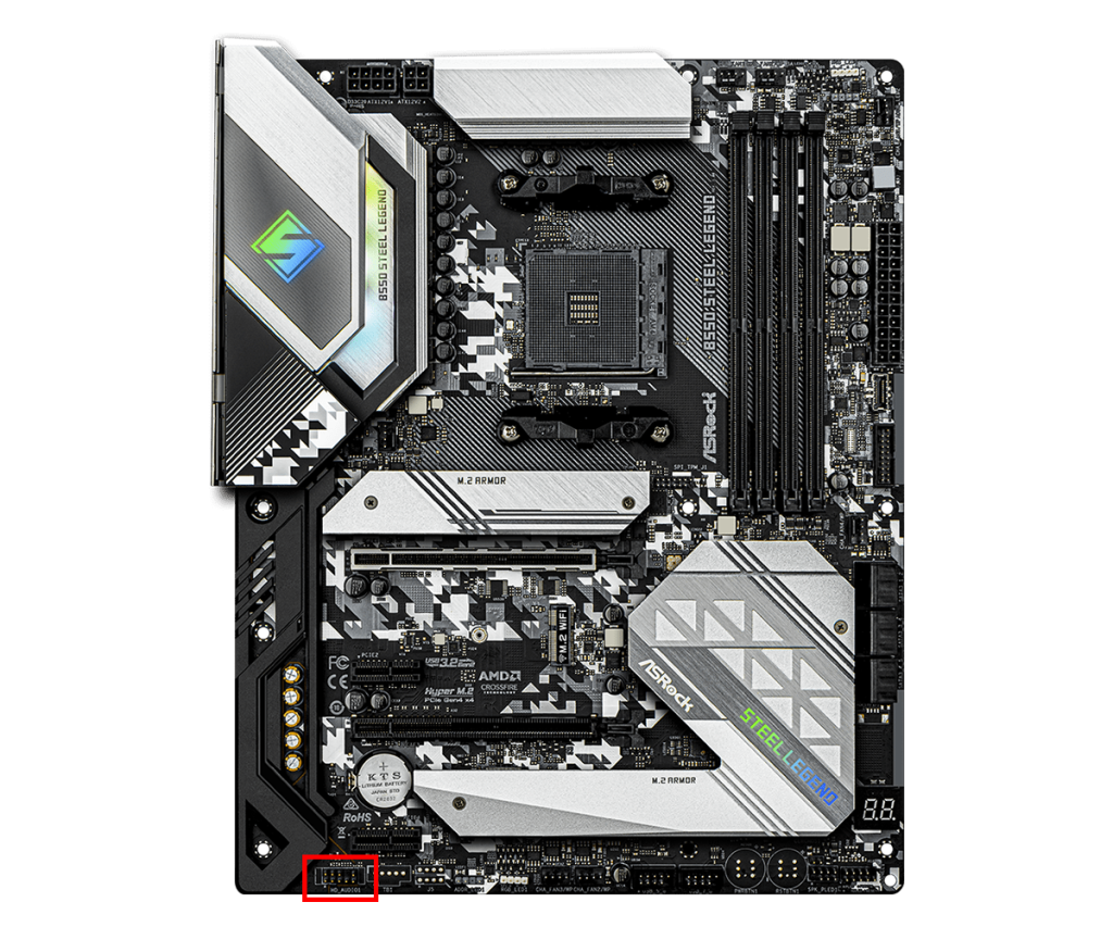
The audio header is a connector on the motherboard for handling audio signals.
It is usually used to connect the headphone and microphone jacks on the front of the case.
The audio header usually has a 10-pin layout and supports standards like HD Audio.
This makes it easy for users to use the PC’s audio features.
Depending on the motherboard design, the audio header may be in a different location, but it is usually on the edge of the motherboard.
Motherboard Back Panel (Input/Output Ports)
The motherboard back panel has various ports such as USB ports and video output terminals.
These ports are exposed at the back of the PC case when the motherboard is installed.
Therefore, the ports available on the back of the PC are determined by the motherboard’s back panel, so check what ports are available before choosing a motherboard.
USB Port
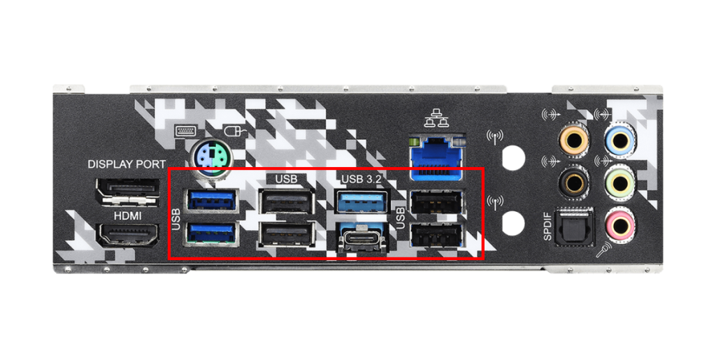
USB ports are located on the motherboard’s back panel and are used to connect various peripherals.
These ports are designed to easily connect many devices such as keyboards, mice, printers, and external hard drives.
There are several versions of USB ports, including USB 2.0, USB 3.0, USB 3.1, and the latest USB 3.2 and USB 4.0.
These versions differ in data transfer speed and power supply capability, with newer versions being faster and more efficient.
USB ports also come in different shapes, such as the standard Type-A port and the smaller, reversible Type-C port.
When choosing a motherboard, it is important to check how many of each USB port version are available.
Generally, there are about 6 to 8 Type-A ports, but Type-C ports are not always included.
If a Type-C port is needed, make sure the motherboard supports it.
Video Output Port
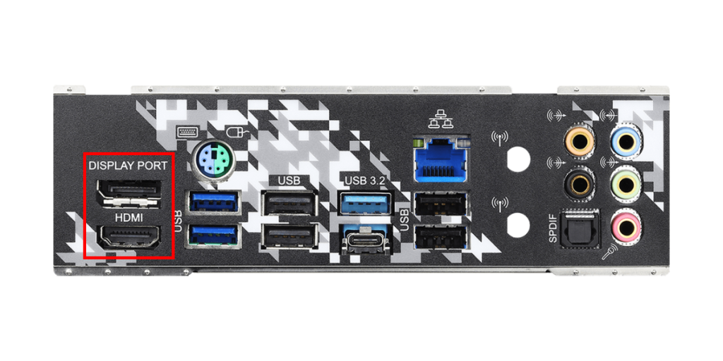
Video output ports are used to output the PC’s video signal to a monitor.
These ports include DisplayPort, HDMI, VGA (D-Sub), and DVI.
Recently, DisplayPort and HDMI are most commonly used, while VGA is sometimes used in business settings.
For custom PCs, it is best to focus on DisplayPort and HDMI and choose a monitor with matching input ports.
The motherboard’s video output ports can only be used if the CPU has an integrated GPU.
If the CPU does not have an integrated GPU, connecting a monitor to these ports will not display any video.
In that case, a graphics card must be installed, and its video output ports should be used.
If the CPU does not have an integrated GPU and no graphics card is installed, the PC cannot output video and cannot be used, so be careful when choosing parts.
LAN Port
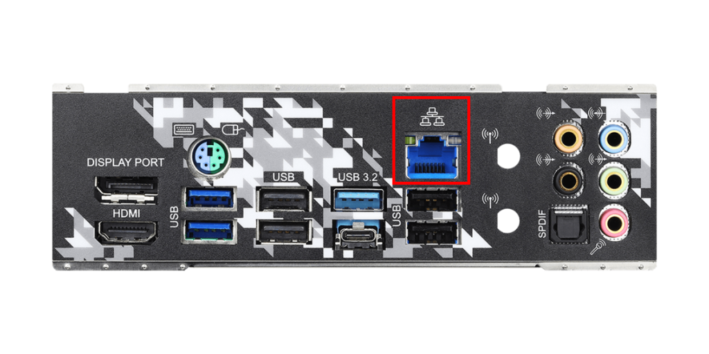
The LAN port is used to connect the computer to a network.
It usually has an RJ-45 connector and allows connection to the internet or local network via a wired LAN cable.
The LAN port affects the stability and speed of the internet connection, which is important for online gaming and large data transfers.
Many motherboards support gigabit Ethernet, with speeds up to 1Gbps.
Some recent high-end motherboards have LAN ports that support 2.5Gbps or higher speeds.
If Wi-Fi is available at home and the motherboard or an expansion card supports Wi-Fi, using the LAN port is not necessary.
However, compared to wireless connections, wired connections are faster and more stable, so choose wired or wireless depending on your needs.
![]() Ken
Ken
Audio Port
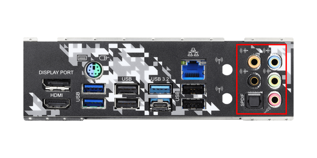
Audio ports are used to connect audio devices such as speakers, microphones, and headphones.
Usually, 3.5mm mini-jacks are used, and they are often color-coded.
The functions of each color are as follows:
| Color | Use | Description |
|---|---|---|
| Green | Line Out / Speaker Output | Main output port for connecting front speakers or headphones |
| Pink | Mic Input | Input port for connecting a microphone |
| Blue | Line In | Port for inputting audio from external audio devices |
| Orange | Subwoofer / Center Output | Output port for connecting a subwoofer or center speaker |
| Black | Rear Speaker Output | Output port for connecting rear (back) speakers |
| Gray | Side Speaker Output | Output port for connecting side speakers, used in 7.1ch surround systems |
Also, recent motherboards may have an optical digital terminal (S/PDIF) for digital audio output.
This allows high-quality digital audio signals to be sent to external audio equipment.
The types and number of audio ports vary by motherboard model, so choose a motherboard that matches the audio devices to be used.
PS/2 Connector

The PS/2 connector is an older type of connector for connecting keyboards and mice.
It is located on the motherboard’s back panel and is characterized by a round 6-pin connector.
Usually, purple is for keyboards and green is for mice.
A port that is half purple and half green, as shown in the image, means it supports both mouse and keyboard.
Before USB became common, the PS/2 connector was the standard connection method, but now USB is mainstream and PS/2 connectors are becoming less common.
Still, PS/2 connections are sometimes supported on some motherboards for compatibility with older hardware or certain BIOS settings.
Names of Motherboard Components
This section explains parts other than slots, connectors, and the back panel.
VRM (Phase)
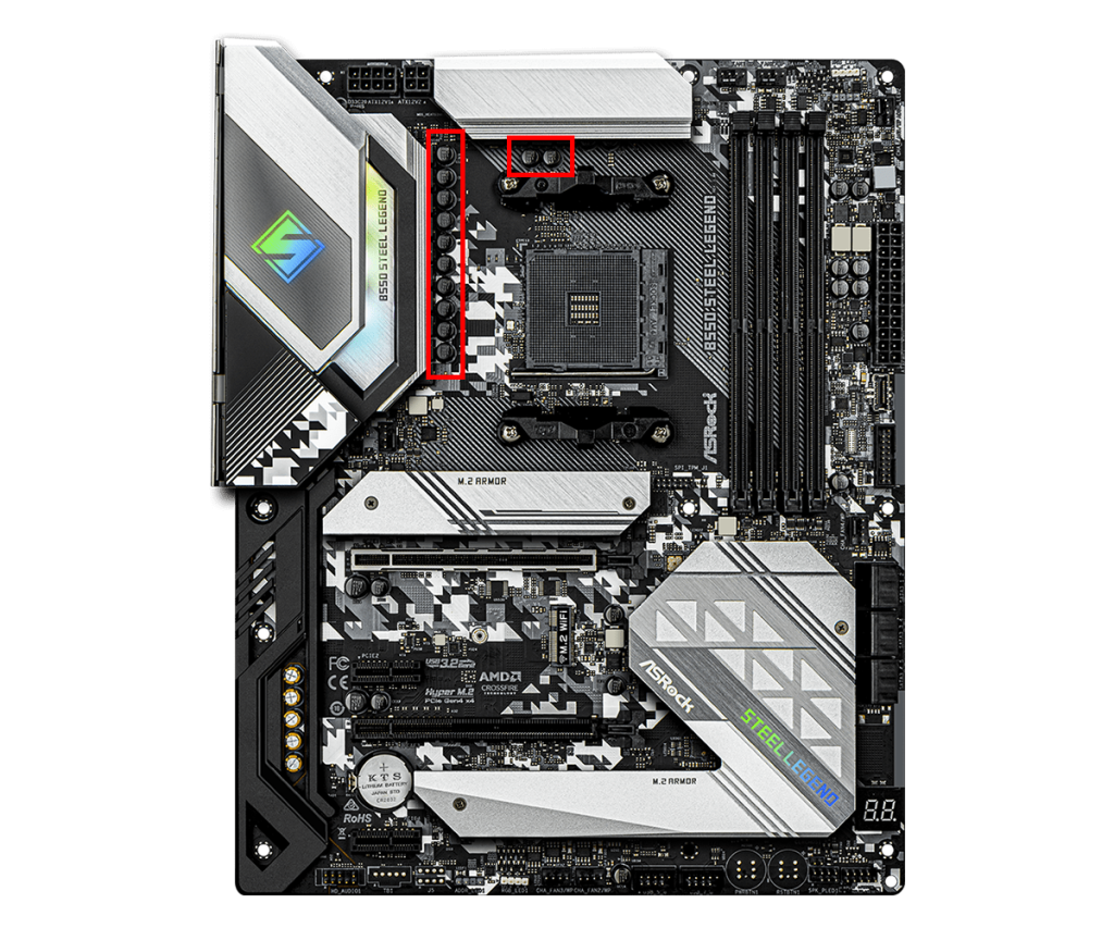
The motherboard’s VRM (Voltage Regulator Module) is a voltage regulation circuit that supplies proper and stable voltage to key parts like the CPU and memory.
It converts the voltage supplied by the power supply unit to the specific voltage levels required by each part, supporting stable operation.
The CPU and memory require very precise voltage, and the VRM converts the input voltage to the required output voltage.
High-performance CPUs or overclocking require a lot of current.
If the VRM quality or phase count is insufficient, power supply becomes unstable, which can cause system crashes or hardware damage.
VRMs are usually made up of multiple circuits called “phases.”
The more phases, the more stable the power supply and the better the heat dissipation.
Generally, more phases allow for finer power control to the CPU and other parts, resulting in better stability and durability.
However, for normal use, it is not necessary to choose a motherboard based on phase count.
Also, motherboards with more phases are more expensive, so for basic tasks or gaming, phase count does not need to be a concern.
Summary: Knowing the Names Makes Assembly Smoother!
This article explained in detail the names and roles of motherboard slots, connectors, and back panel ports.
Images were included to help visualize where each socket and connector is and what they look like, so it should be easier to understand.
When choosing parts or assembling a custom PC, many different names are used, so knowing the ones introduced here should help things go smoothly.
This article also explains motherboard standards, the names of each component, and how to choose based on performance and compatibility.
≫ Related article: How to Choose a Motherboard for a Custom PC [Performance / Features / Compatibility]
Select PC parts and online stores to instantly generate an estimate, check compatibility, and calculate power requirements. You can save up to five different builds, making it easy to try out multiple configurations.
≫ Tool:PC Parts Estimation & Compatibility Check Tool